Electronics is really a very interesting field of Science and Technology since its really vast and deals with a lot of projects and DIY hacks and a lot more interesting stuff. Its really a great hobby in fact, be it building your own variable power supplies, or building your own crazy Robot, its time we become “EVIL MAD SCIENTISTS”.
To get started we have to learn about the various components and their functions. So lets get you briefed thoroughly.
All budding engineers and electronics hobbyists out there, get ready for an in depth analysis of the most common electronics components for you to get started.
RESISTORS
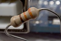
Resistors offer opposition to current, dissipating the opposed power as heat. Limiting current is a vital function in any circuit, so every electronic product has resistors. They come in many shapes and sizes, but those with leads are easily identifiable by their color bands indicating the resistance value in ohms. Some large resistors are marked numerically, as are some of the tiny surface-mount parts.
The basic type of resistor, found in virtually everything, is the carbon composition resistor. Made from a carbon compound, these resistors run the full range of values, from less than 1 Ù (ohm) to 10 MÙ (megohms, or millions of ohms). Most you’ll see will be over 10 Ù and under 1 MÙ. The tolerance for standard carbon comp resistors is ± 5 percent. That is, the measured value should be no more than 5 percent high or low of the stated resistance.
Some applications require the use of wire-wound resistors. These look a lot like carbon comp parts, but you can see the coil of wire under the paint on the body.
Wire-wound resistors can dissipate more heat than can carbon comps. They also can be manufactured to very tight tolerances, but they have some inductance, since they are coils, and are ill suited to high-frequency circuits where the inductance might matter. The two types should not be interchanged.
In addition to the resistance value, the power dissipating capability of a resistor, measured in watts, is an important factor. Since power is dissipated as heat, knowing how much heat the part can take before disintegrating is vital. Standard carbon comps are rated at 1/4 watt, with some slightly larger ones able to dissipate 1/2 watt. Very tiny ones with leads are rated at 1/8 watt, while surface-mount versions typically vary from 1/8 watt down to 1/32 watt.
Other resistor formulations include carbon film, metal film and metal oxide. Carbon film types introduce a bit less noise into the circuit and are used in areas where that’s a significant issue. Metal film and metal oxide parts have tighter tolerances, in the range of 1 or 2 percent of stated value. Some circuits require that for proper operation.
Symbol
Markings
The use of color-coding dates back to the vacuum tube days, when resistors got so hot that printed numbers would evaporate. To read the color code, you must first determine which end of the resistor is the start and which is the far end. Look for a gold or silver band; that’s the tolerance marking, indicating the far end, and there’s usually a little extra space between that band and the others. The first digit will be at the end farthest from the tolerance band.
Each number is represented by a color. The scheme is as follows:
Black 0 Green 5
Brown 1 Blue 6
Red 2 Violet 7
Orange 3 Gray 8
Yellow 4 White 9
The tolerance bands at the far end are as follows:
Brown ± 1 percent
Red ± 2 percent
Gold ± 5 percent
Silver ± 10 percent
To determine a resistor’s value, read the first two bands as numbers. The third band is a multiplier, indicating how many zeros you need to tack on to the numerical value. So, for instance, red-red-brown would be 2, 2, and one zero, or 220 ohms. Yellow-violet-orange would be 4, 7, and three zeros, or 47,000 ohms, a.k.a. 47 KΩ. Be careful not to confuse a black third band with a zero; it means no zeros.
To determine a resistor’s value, read the first two bands as numbers. The third band is a multiplier, indicating how many zeros you need to tack on to the numerical value. So, for instance, red-red-brown would be 2, 2, and one zero, or 220 ohms. Yellow-violet-orange would be 4, 7, and three zeros, or 47,000 ohms, a.k.a. 47 KÙ. Be careful not to confuse a black third band with a zero; it means no zeros.
Uses
Resistors are found in just about every circuit. They limit the current that can pass through other parts. For instance, transistors amplify a signal by using it as a control for a larger current provided by the power supply, somewhat like the handle on a spigot controls a large flow of water. A resistor between the supply and the transistor sets how much current the transistor has to control. Without the resistor, the transistor would have to handle all of the supply’s current and would self-destruct.
What Kills Them
Resistors rarely fail on their own. Heat caused by passing too much current burns them out, sometimes literally. Carbon composition resistors can go up in flames or become a charred lump when a short in some other part pulls a lot of current through them. It’s not uncommon to see one with a burn mark obscuring the color bands.
Out-of-Circuit Testing
Use your DMM’s ohms scale to see if the resistance is within the specified tolerance range. Most resistors do better than their tolerances, but expect a small difference between what’s on the code and what you measure.
When the resistor is charred beyond your being able to read the color code, it can be a real problem unless you have the unit’s schematic diagram. Luckily, resistance values follow a standard pattern, because there would be no point in producing resistors whose values fell within another resistor’s tolerance range. So, you may be able to infer a burned-out band’s value from others that can still be seen. If you ever need it, you can look up the list of standard values online.
CAPACITORS
Capacitors consist of two plates separated by an insulator. A charge builds up on the plates when voltage is applied, which can then be discharged back into the circuit. Capacitors come in many types, including ceramic, electrolytic, tantalum, polystyrene (plastic) and trimmer (variable).
Symbols
Markings
Most capacitors are marked in straightforward manner, with numbers followed by μf (microfarads, or millionths of a farad) or pf (picofarads, or trillionths of a farad). Leading zeros to the left of the decimal point are not shown, so we won’t use them here either. Some European gear has caps marked in nf (nanofarads, or billionths of a farad). Thus, a cap marked 1 nf = .001 μf. Some capacitors are marked with three numbers, with no indication of μf, nf or pf. With these, the last number is a multiplier, indicating how many zeros you need to tack on, starting from picofarads. For instance, a cap marked 101 is 100 pf, because there is one zero after the two numbers indicating the value. A marking of 102, then, is 1000 pf, or .001 μf. And 103 is 10,000 pf or .01 μf, and so on.
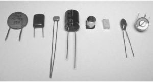
Ceramic disc, plastic, electrolytic, surface-mount electrolytic, tantalum, and trimmer capacitors
Here’s a handy list:
- XX0 = less than 100 pf. The two Xs are the value in pf. Sometimes there’s no zero on the end. A tiny cap marked 27 is 27 pf. One marked 270 is also 27 pf.
- XX1 = value X 10 pf
- XX2 = .00XX μf
- XX3 = .0XX μf
- XX4 = .XX μf
- XX5 = X.X μf
- XX6 = XX μf
Any value greater than these will be marked directly in μf, as in “2000 μf.”
On ceramic disc capacitors, you may also see a marking like N750. This specifies the temperature coefficient, or how much the capacitance drifts with temperature and in which direction. Keep an eye out for NP0, which means no drift in either direction. NP0 caps are used in time constants and tuned circuits so they won’t change frequency as the unit warms up. Should you ever need to replace an NP0 cap, be sure to use the same type.
Polarized capacitors are marked for their polarity. With can-style electrolytics, the marking is a long arrow or black line, and it indicates the negative lead. Some very old electrolytics may show a + sign instead, indicating the positive lead, but they haven’t been made that way for many years. Look for them in antique radios and such.
Tantalum electrolytics, which look like little dipped candy drops with wires, denote the positive lead with a + sign, or sometimes a red or silver dot.
Figure 7-1 Ceramic disc, plastic, electrolytic, surface-mount electrolytic, tantalum, and trimmer capacitors.
Uses
Different styles of capacitors cover various ranges and are used for different purposes. Here are the common ones:
Ceramic• These cover the very small values, from a few pf up to around .1 μf, and are used in resonant radio circuits and bypass applications.
Plastic• These start at around .001 μf (1000 pf) and may go as high as .47 μf or so. They are used for bypass and coupling, and are sometimes found in time constants because of their excellent stability over a wide range of temperatures.
Electrolytic• These start at around .47 μf and cover the highest ranges, on up to tens of thousands of μf. They are used for coupling and filtering.
Tantalum• These range from .1 μf to around 47 μf and are a special type of electrolytic capacitor with lower impedance at high frequencies. They are used in filtering and bypass applications when high frequencies are present.
Trimmer• These range from the low pfs to around 200 pf and are used as frequency adjustments for tuned (resonant) circuits and oscillators.
What Kills Them
Different styles of capacitors fail for different reasons, depending on how they’re used and to what conditions they’re subjected. Generally, application of a voltage above the cap’s ratings can punch holes in the dielectric (insulating) layer, heat can dry or crack them, and some wear out with age.
Ceramic and Plastic These very rarely fail. I’ve found two bad ceramics and one bad plastic cap! It just doesn’t happen. If these caps appear unharmed, they are almost certainly okay.
Electrolytic These are the most failure-prone components of all. Part of their charge-storing layer is liquid, and it can dry out, short out, swell and even burst the capacitor’s seals and leak out. Heat, voltage and age all contribute to their demise. The constant charging and discharging as they smooth ripple currents in normal operation
Tantalum These use a solid electrolyte in the dielectric layer that is quite thin. Consequently, they are prone to shorts from even momentary voltage spikes exceeding their voltage ratings and punching holes in the layer. And they are even less tolerant of reverse current than are standard electrolytics.
Trimmer Trimcaps use a plastic or ceramic insulating layer that is very reliable. They rely on a mechanical connection, though, between the rotating element and the base, making them prone to failure from corrosion over a period of many years. Sometimes rotating the adjustment through its range a few times can clear it up, but doing so causes loss of the initial setting, requiring readjustment afterward. Never spray the plastic variety with cleaner spray, as it may damage the dielectric layer and destroy the component.
Out-of-Circuit Testing
To test a capacitor after removal from the circuit, use your cap meter. If you don’t have one, you can use your DMM’s ohms scale to check for shorts. Small-value caps will appear open whether they are or not; they charge up too quickly for you to see the voltage rising.
For electrolytics, do a quick test with an analog VOM, watching for the initial needle swing and slow release back toward infinity. Make sure the cap is discharged before you try to test it. With a polarized cap, connect the test leads + to + and – to –. Most polarized caps will survive a reversed test, but tantalums may not; even momentary reversed voltage can short them out.
Diodes
Diodes are one-way valves. Current can flow from their cathodes (–) to their anodes (+) but not the other way. They are made from silicon slabs “doped” with materials that cause the one-way current flow, with two dissimilar slabs touching at a junction point. Large diodes used in power supplies are called rectifiers, but they do the same thing. Two of them in one package, sharing one common terminal (for a total of three leads), are called a double diode, or double rectifier. Four of them arranged in a diamond-like configuration are called a bridge rectifier, whether they are separate parts or integrated into one package.
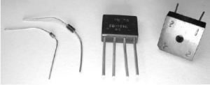
Diode, rectifier, and bridge rectifiers
Symbols
Markings
Single diodes and rectifiers have a band at one end indicating the cathode. They are marked by part number, which does not indicate their operating parameters like maximum forward and reverse operating voltages and maximum current. To get those, you must look up the part number in a book or online.
Bridge rectifiers may be marked for peak forward voltage and current, but they often have part number markings or none at all. Sometimes you’ll see “~” at the AC inputs and “+” and “–” at the DC outputs.
You may see a marking like 200 PIV, for peak inverse voltage. This is the maximum voltage the diode can withstand in the reverse (nonconducting) direction before breaking down and allowing the voltage to pass. Exceeding the PIV rating usually destroys the diode.
Uses
Diodes and rectifiers are common parts in pretty much every electronic product. Small-signal diodes rectify signals for detection of the information they carry, as in a radio, and direct control voltages that turn various parts of the circuitry on and off. They may also be used as biasing elements, providing a specific current to the inputs of transistors and other amplifying elements, keeping them slightly turned on so that they can conduct over the required portion of the input signal’s waveform. Light-emitting diodes, or LEDs, are used as indicators on control panels, and bright white LEDs backlight newer LCD screens in many products, from laptops, netbooks, and tablet computers to large TVs.
Rectifiers convert incoming AC power to DC. They convert the pulses in a switching power supply’s transformer back to DC as well. Bridge rectifiers are commonly used to change AC line current to DC by directing opposite sides of the AC waveform to the appropriate + and – output terminals.
What Kills Them
Diodes and rectifiers can fail from voltage exceeding their limits, but the most common cause is too much current and the heat it produces. Sometimes they just fail with age, too. Failure modes include opens, shorts and leakage.
Out-of-Circuit Testing
Most DMMs include a diode test function that shows the voltage drop across the part, indicating whether it is passing current. Be sure to test the diode in both directions. It should show a drop of around 0.6 volts in one direction and appear open in the other. An open reading will show the applied test voltage, the same as when the meter’s leads are unconnected to anything. Even a small voltage drop in the reverse direction suggests a leaky diode that should be replaced.
With an analog VOM, you can use the resistance ranges to get a good idea of a diode or rectifier’s condition, but small leakage currents are hard to detect. With either type of meter, you’re most likely to see a total failure, either open or shorted, if the part is bad. Leaky diodes are rare, but not so rare that you shouldn’t keep the possibility in mind.
Inductors and Transformers
Inductors, or coils, generate a magnetic field when current passes through them. When the current through the inductor stops or changes direction, the field collapses and creates a current in the wire, opposing the changes. The effect is to store some of the energy and put it back into the circuit.
Coils may be wound on nonferrous cores having no effect on the magnetic field, or they may be wound on iron cores that play a significant role in the inductor’s behavior. Two inductors wound on the same iron core can be used to convert one voltage and current to another by creating a magnetic field in one coil and using it to generate a current in the other coil, which may have a different number of turns of wire, thus creating a different voltage. This arrangement is called a transformer.
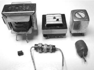
Inductors and transformers
Symbols
Markings
Many coils are not marked. Some small ones are encapsulated in plastic or ceramic and marked in μh (microhenries, or millionths of a henry) or mh (millihenries, or thousands of a henry).
Uses
Inductors and transformers are used to convert voltages; to couple signals from one stage to another, especially in radio equipment; and to filter, or smooth, voltage variations. They are also essential parts of many resonant circuits, working together with capacitors to establish time constants.
Their inherent opposition to rapid voltage change makes coils useful for isolating radio-frequency signals within circuit stages while allowing DC to pass. When used in this manner, coils are called chokes because they choke off the signal. Look for them where DC power feeds from the power supply into RF stages.
What Kills Them
In low-power circuits, coils are highly reliable. Failure is pretty much always due to abuse by other components. It’s very rare for small-signal inductors to fail, since little current passes through them. In circuits where significant supply current is available, a shorted semiconductor can pull enough through the inductor feeding it to blow the coil. If you find an open inductor, assume something shorted and killed it.
The windings in power transformers sometimes open when too much current overheats them and melts the wire. Often, the primary (AC line) side will burn out even though the excessive current draw is on the other side of the transformer, somewhere in the circuitry. They may also short to the iron core. The insulation of the windings in high-voltage transformers can break down and arc over to other windings, create a short between windings, or arcing and shorts to the core.
Out-of-Circuit Testing
Use your DMM to test for continuity from one end of a coil or section of a transformer to its other end. You can also use the ohms scale to check for shorts from windings to the core and between unconnected windings.
It’s very hard to tell whether windings are shorted to each other in the same coil. Using the ohms scale, the difference can be so slight that it’s undetectable. If you have an inductance meter and know the correct inductance, that will give you some idea. With unmarked coils and just about all transformers, though, you won’t know what the inductance should be without access to an identical part for comparison. In some circuits, such as LCD back lighting inverters, there can be two identical transformers, so you may be in luck.
Transistors
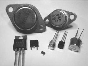
Along with integrated circuits, transistors are the active elements that do most of the work in circuits, amplifying, processing and generating signals, switching currents and providing the oomph needed to drive speakers, headphones, motors and lamps.
Transistors
Transistors act like potentiometers, but instead of your hand’s turning the shaft, a signal does. The current fed by the power supply through the pot can be much greater than that required to turn the shaft, providing gain, or amplification, as the wiggling signal molds a bigger version of itself from the power supply’s steady DC.
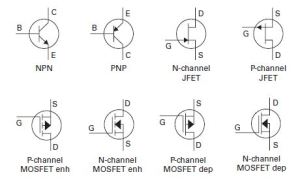
There are thousands of subtypes of transistors, but most fall into three categories: bipolar, JFET and MOSFET.
Bipolar transistors are the standard types used in products since the 1950s. They come in two polarities, NPN and PNP, and consist of three elements joined by two junctions. The three elements are the base, emitter and collector, each with its own lead. Current passing between the base and the emitter permits a much larger current to pass between the collector and the emitter, with one of them being fed from the power supply.
As you can see, transistors have many parameters, so it’s not surprising that there are thousands of subtypes with different gains, power dissipation capabilities, frequency limits and so on. Some are similar enough that they can be interchanged
in many circuits, but most are not. To replace one part number with another, you need a transistor substitution book or an online cross-reference guide.
Symbols
Markings
Transistors are marked by part number, called a type number. There are thousands of these numbers! Some numbers indicate whether a bipolar part is NPN or PNP. If the number starts with 2SA or 2SB, it’s PNP. If it starts with 2SC or 2SD, it’s NPN. Sometimes the 2S will be left off, and there are plenty of type numbers that don’t follow this scheme at all. A 3N indicates a FET, but some of them have numbers starting with 2N, and there are lots of other kinds of numbers for these too.
Some transistors have house numbers, which are proprietary numbering schemes used by different manufacturers to mean different things. There is no way to ascertain what the industry-standard number would be for such a part. Tiny, surface-mount transistors often have no numbers at all.
The arrangement of the leads varies with transistor type. Small Japanese parts with leads are usually laid out ECB, left to right, while American parts are often EBC. Metal-encased power transistors have only two leads and use the metal casing as the collector. Plastic power transistors are usually BCE, with the metal tab, if there is one, being C.
Uses
In discrete (nonintegrated-circuit) stages, transistors are the active elements doing the work, with passive parts like resistors and capacitors supporting their operation. You’ll see this kind of construction in radio receivers, audio amplifiers and some sections of many other products. In stages where an IC is at the center of the action, transistors frequently do the interfacing between the IC and other parts of the circuitry, especially areas requiring more current than an IC can supply. MOSFETs are used as switches, permitting the microprocessor to turn power on and off to various parts of the circuitry. Some of their very sensitive varieties are used to amplify and detect radio signals. Many audio power amplifier output stages are made from bipolar transistors. It’s hard to find any function that transistors don’t do. After electrolytic capacitors and bad connections, transistors will be the focus of much of your repair work.
What Kills Them
Transistors are not especially fragile, but they work hard in many circuits and fail more often than do most components. Overheating due to excessive current will burn them out, as will too high a voltage. MOSFETs are particularly prone to shorts from static electricity. Sometimes the internal structure of a transistor develops a tiny flaw, and the thing self-destructs with no apparent cause. In fact, many random product failures occur for precisely this reason. You change the part and the unit works again, and you never find any reason for the dead transistor.
Out-of-Circuit Testing
If you have a transistor tester, use it! Nothing’s easier than hooking up the leads and getting the test result. If you don’t have one, you can use your DMM’s diode test or, lacking that, the ohms scale to check for shorts. If you get near-zero ohms between any two leads, check in the other direction. If it’s still near zero, the part is shorted.
Checking for opens is a bit more complicated, because some combinations of terminals should look open, depending on to what the control terminal is connected. Connecting the base of a bipolar transistor to its collector should result in its turning on, showing measurable resistance between the emitter and collector in one direction. Connecting the base to the emitter should turn it off.
Similarly, connecting the gate of a FET to its drain should turn it on, and connecting it to the source should turn it off. However, some FETs are symmetrical and will turn on with the gate connected to either of the other terminals, as long as the polarity of the applied voltage is what the gate needs. And the whole situation is complicated by the enhancement/depletion mode issue, because a depletion mode FET will stay on. FETs are not easy to test with an ohmmeter!
