This simple, wearable circuit uses an operational amplifier (or “op-amp”) chip to convert sound into light. An LM324 op-amp and a transistor boost input from a mini condenser microphone to light a series of LEDs. Watch it blink to the beat of your favorite music.
STEPS
Components Required
- Battery, 9V (1)
- Solder, lead-free (1)
- Battery snap, 9V (1)
- Hookup wire, 22 gauge, multiple colors (1)
- PC board, grid style, with 371 holes (1)
- Resistor assortment, 500 piece (1)
- Transistor, NPN, 2N4401 (1)
- Microphone condenser element (1
- Capacitor, 0.1 µF ceramic (100 nF, capacitor code 104) (1)
- Capacitor, 1.0µF non-polarized electrolytic (capacitor code 105) (1)
- Op-Amp chip, Quad, LM324 (1)
- LED 5mm (1)
Step #1: Gather the parts

- The electret microphone element is polarized, so be careful not to reverse the connections. The ground leg is the one with the 3 silver traces running to the case (second photo).
- To identify resistor values from their color codes, you can use this online calculator.
- The LM324 chip has four op-amps, but this circuit only requires two of them.
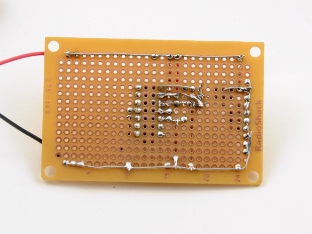
Step #2: Solder the mic, socket, and power


- Follow the schematic to connect all components, starting with the microphone, chip socket, and battery holder.
- It is useful to strip some wire and create a power “bus” consisting of V+ and Ground (-) lines running down the underside of the board on opposite sides. Solder these to the red (+) and black (-) wires of the battery holder, respectively.
- On the schematic, the LN324 chip is drawn functionally, using two separate amplifier symbols (the triangles). Both of these represent the same component, and you need only one connection each between Pin 4 and V+, and Pin 11 and Ground.
Step #3: Add the input stage resistors and capacitors

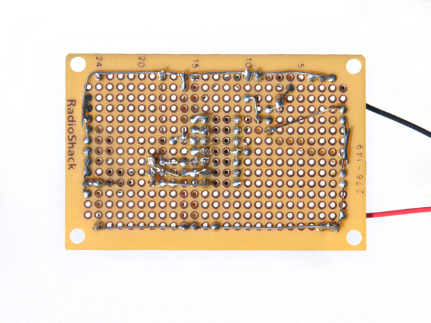
- When you are following a schematic, it’s useful to print it out and mark off each connection as you make it. Quite often your circuit board layout will not resemble the diagram, and so, doing this lets you know how much you have completed.
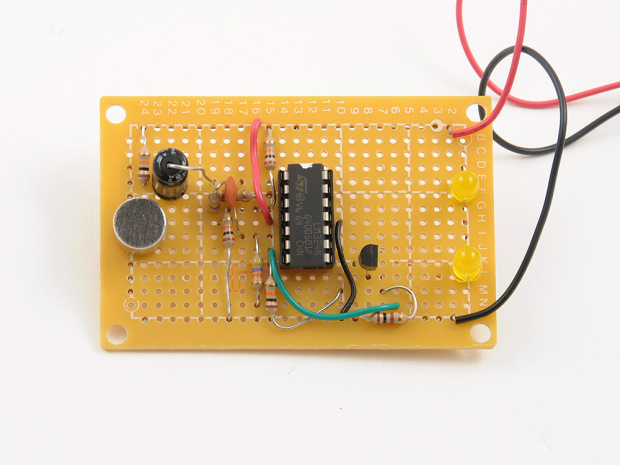
- In the second photo here, you can see most of the input stage components added. These are: Microphone, 3x 10kΩ resistors (Brown, Black, Orange, Gold), 2.2kΩ resistor (Red, Red, Red, Gold), 470kΩ resistor (Yellow, Violet, Yellow, Gold), 1µF capacitor and 01.µF capacitor.
- Plug the LM324 chip into the socket. Note the chip’s orientation. With the notch pointing up, Pin 1 is top left corner, and the pins are numbered counter-clockwise.
- Power it up by inserting the batteries. If nothing starts smoking, that’s a good sign!
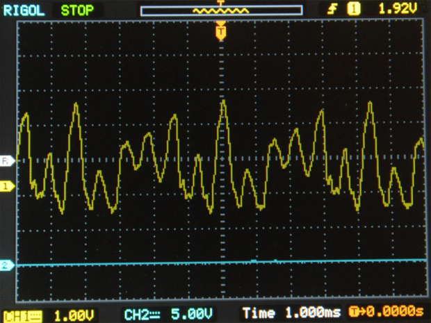
- To check the output from the first amplifier, I hooked up an oscilloscope to the right hand leg of the 0.1µF capacitor. This showed a sound wave when I spoke – so far, so good!
Step #4: Add the the second stage resistors

- We’re getting really close now. Add the remaining resistors: 47kΩ ohm (Yellow, violet, orange, gold), 10kΩ ohm (Brown, black, orange, gold), 100Ω (Brown, black, brown, gold).
- Solder a connecting wire from chip Pin 7 to where you’ll put the transistor, which we’ll add in the next step.
- All that remains is to add the transistor and the LEDs.
Step #5: Final assembly – and testing!

- Finish up by connecting the transistor (note the orientation) and the LEDs, connected in series.
- Now we should be able to turn the Wearable Light Organ on and see something happening.
- You can see a little YouTube movie of the device in action here.
