 To test the accuracy of a new fingerprint scanner, researchers typically run millions of known fingerprint images through the system’s matching software. But this testing procedure can’t quite mimic real operating conditions, as a 2-D image fed into a program is fundamentally different than a 3-D finger pressed to a sensor. Continue reading
ROBOTS DETECTS LANDMINES FROM FAR, FAR AWAY

In 2012, Clearpath Robotics decided to give away a customized Husky UGV to a worthy cause, and what could be more worthy than keeping us humans from getting blown up. The University of Coimbra in Portugal has taken its free Husky and turned it into an clever little autonomous mobile mine detector.
Huskies don’t come stock with the ability to detect mines. Or rather, they may be able to detect one single mine once. By accident. Catastrophically. To get the robot all set to not blow itself (or anyone else) into tiny little chunks, the team at Coimbra added sensors for navigation and localization (GPS, stereo vision, and a laser), as well as (more importantly) a customized two-degrees-of-freedom arm equipped with both a metal detector and a ground penetrating radar system. Continue reading
ORGAN IMPLANTS COULD POWER PACEMAKERS

Injectable medical sensors and embedded implants are becoming less of a sci-fi trope as they manifest into reality. While most devices are either designed to be charged wirelessly or simply react with bodily fluids, cyborgs of the future may power such implants by sewing energy harvesters directly onto their internal organs.
A team of researchers from several U.S. academic institutions and one from China created a small, piezoelectric device that, when attached to a constantly moving organ — such as the heart, lung or diaphragm — can harness enough electricity to power a pacemaker or other medical implant.
The device incorporates lead zirconate titanate nanoribbons that are housed in a flexible, biocompatible plastic. Also included is an integrated rectifier that converts the electric signals, plus a miniature rechargeable battery. Constant motion of the organ causes the nanoribbons to bend, thus creating small amounts of electricity. Continue reading
INTEGRATED CIRCUITS
Introduction
Integrated circuits (ICs) are a keystone of modern electronics. They are the heart and brains of most circuits. They are the ubiquitous little black “chips” you find on just about every circuit board. Unless you’re some kind of crazy, analog electronics wizard, you’re likely to have at least one IC in every electronics project you build, so it’s important to understand them, inside and out.

Integrated circuits are the little black “chips”, found all over embedded electronics.
An IC is a collection of electronic components – resistors, transistors, capacitors, etc. – all stuffed into a tiny chip, and connected together to achieve a common goal. They come in all sorts of flavors: single-circuit logic gates, op amps, 555 timers, voltage regulators, motor controllers, microcontrollers, microprocessors, FPGAs…the list just goes on-and-on.
Covered in this Tutorial
- The make-up of an IC
- Common IC packages
- Identifying ICs
- Commonly used ICs
Inside the IC
When we think integrated circuits, little black chips are what come to mind. But what’s inside that black box?

WHAT IS ARDUINO? – LEARNING BY DOING
Introduction
Arduino is an open-source platform used for building electronics projects. Arduino consists of both a physical programmable circuit board (often referred to as a microcontroller) and a piece of software, or IDE (Integrated Development Environment) that runs on your computer, used to write and upload computer code to the physical board.
The Arduino platform has become quite popular with people just starting out with electronics, and for good reason. Unlike most previous programmable circuit boards, the Arduino does not need a separate piece of hardware (called a programmer) in order to load new code onto the board–you can simply use a USB cable. Additionally, the Arduino IDE uses a simplified version of C++, making it easier to learn to program. Finally, Arduino provides a standard form factor that breaks out the functions of the micro-controller into a more accessible package. For more info about the Arduino, check here and here.

This is an Arduino Uno
The Uno is one of the more popular boards in the Arduino family and a great choice for beginners. We’ll talk about what’s on it and what it can do later in the tutorial.
This is a screenshot of the Arduino IDE:

Believe it or not, those 10 lines of code are all you need to blink the on-board LED on your Arduino. The code might not make perfect sense right now, but our tutorials on getting started with Arduino will get you up to speed in no time!
In this tutorial, we’ll go over some of the things you can do with an Arduino, what’s on the typical Arduino board, and some of the different kinds of Arduino boards.
We will learn:
- What you might use an Arduino for
- What is on the typical Arduino board and why
- The different varieties of Arduino boards
- Some useful widgets to use with your Arduino
What does it do?
The Arduino hardware and software was designed for artists, designers, hobbyists, hackers, newbies, and anyone interested in creating interactive objects or environments. Arduino can interact with buttons, LEDs, motors, speakers, GPS units, cameras, the internet, and even your smart-phone or your TV! This flexibility combined with the fact that the Arduino software is free, the hardware boards are pretty cheap, and both the software and hardware are easy to learn has led to a large community of users who have contributed code and released instructions for a huge variety of Arduino-based projects.
The Arduino can be used as the brains behind almost any electronics project.
And that’s really just the tip of the iceberg – if you’re curious about where to find more examples of Arduino projects in action, here are some good resources for Arduino-based projects to get your creative juices flowing:
What’s on the board? Continue reading
BATTERY TECHNOLOGY
Battery Options

There are a multitude of different battery technologies available. There are some really great resources available for the nitty gritty details behind battery chemistries. Wikipedia is especially good and all encompassing. This tutorial focuses on the most often used batteries for embedded systems and DIY electronics.
Terminology
Here are some terms often used when talking about batteries.
Capacity – Batteries have different ratings for the amount of power a given battery can store. When a battery is fully charged, the capacity is the amount of power it contains. Batteries of the same type will often be rated by the amount of current they can output over time. For example, there are 1000mAh(milli-Amp Hour) and 2000mAh batteries.
Nominal Cell Voltage – The average voltage a cell outputs when charged. The nominal voltage of a battery depends on the chemical reaction behind it. A lead-acid car battery will output 12V. A lithium coin cell battery will output 3V.
The key word here is “nominal”, the actual measured voltage on a battery will decrease as it discharges. A fully charged LiPo battery will produce about 4.23V, while when discharged its voltage may be closer to 2.7V.
Shape – Batteries come in many sizes and shapes. The term ‘AA’ references a specific shape and style of a cell. There are a large variety.
Primary vs. Secondary – Primary batteries are synonymous with disposable. Once fully-drained, primary cells can’t be recharged (reliably/safely). Secondary batteries are better known asrechargeable. These require another power source to fully charge back up, but they can fully charge/discharge many times over their life. In general primary batteries have a lower discharge rate, so they’ll last longer, but they can be less economical than rechargeable batteries.
| Battery Shape | Chemistry | Nominal Voltage | Rechargable? |
|---|---|---|---|
| AA, AAA, C, and D | Alkaline or Zinc-carbon | 1.5V | No |
| 9V | Alkaline or Zinc-carbon | 9V | No |
| Coin cell | Lithium | 3V | No |
| Silver Flat Pack | Lithium Polymer (LiPo) | 3.7V | Yes |
| AA, AAA, C, D (Rechargeable) | NiMH or NiCd | 1.2V | Yes |
| Car battery | Six-cell lead-acid | 12.6V | Yes |
PULL UP RESISTOR
Introduction

Pull-up resistors are very common when using microcontrollers (MCUs) or any digital logic device. This tutorial will explain when and where to use pull-up resistors, then we will do a simple calculation to show why pull-ups are important.
What is a Pull-up Resistor
Let’s say you have an MCU with one pin configured as an input. If there is nothing connected to the pin and your program reads the state of the pin, will it be high (pulled to VCC) or low (pulled to ground)? It is difficult to tell. This phenomena is referred to as floating. To prevent this unknown state, a pull-up or pull-down resistor will insure that the pin is in either a high or low state, while also using a low amount of current.
For simplicity, we will focus on pull-ups since they are more common than pull-downs. They operate using the same concepts, except the pull-up resistor is connected to the high voltage (this is usually 3.3V or 5V and is often refereed to as VCC) and the pull-down resistor is connected to ground.
Pull-ups are often used with buttons and switches.

MAKE A SIMPLE 12 VOLT POWER SUPPLY


Have you ever needed a 12 volt power supply that can supply maximum 1 amp? But trying to buy one from the store is a little too expensive?
Well, you can make a 12 volt power supply very cheaply and easily!
Step 1: Things that you will need…

Things that you will need to make this power supply is…
- Piece of protoboard
- Four 1N4001 diodes
- LM7812 regulator
- Transformer that has an output of 14v – 35v AC with an output current between 100mA to 1A, depending how much power you will need.
- 1000uF – 4700uF capacitor
- 1uF capacitor
- Two 100nF capacitors
- Jumper wires (I used some plain wire as jumper wires)
- Heatsink (optional)
Step 2: And the tools…
Also you will need the tools to make this power supply…
- Soldering iron
- Wire cutters
- Wire strippers
- A thing you can cut protoboard tracks.
- Hot glue (To hold components down and make the power supply physically strong and sturdy.)
- And some other tools that you might find helpful.
Okay, I think that is about it, lets get to work!
Step 3: Schematic and others…


If you want a 5 volt power supply, just simply replace the LM7812 to a LM7805 regulator.
Datasheet for LM78XX
Datasheet for LM78XX
If you are going to pull out about 1 amp from this power supply, you will need a heatsink for the regulator, otherwise it will generate very high temperatures and possibly burn out…
However, if you are just going to pull out a few hundred milliamps (lower than 500mA) from it, you won’t need a heatsink for the regulator, but it may get a little bit warm.
Also, here’s the schematic…
I also add in an LED to make sure the power supply is working. You can add in an LED if you want.
Step 4: Make it!

Make sure you get good solder joints and no solder bridges, otherwise your power supply won’t work!
Step 5: Test it!

After you had built your power supply, test it with your multimeter to make sure they are no solder bridges.
After you tested it, put it in a plastic box or something to protect you from shocks.
But do not operate the power supply like I did, it is very dangerous because of the mains voltage on the transformer, you or somebody will get badly shocked!
My power supply has 11.73v output, not too bad, I don’t need it to be exactly 12v…
Step 6: Done…
FIRST 3-D PRINTED SPEAKER

A loudspeaker playing a clip of President Barack Obama talking about 3-D printing in his State of the Union speech might not seem so remarkable—except that the loudspeaker represents one of the first 3-D printed consumer electronic devices in the world.
The 3-D printed loudspeaker is more expensive, took longer to make, and is of a lower quality than a typical mass-produced speaker, said Hod Lipson, an associate professor of mechanical and aerospace engineering at Cornell University. But he described his lab’s demonstration to IEEE Spectrum as providing a “glimpse of the future” by showing that 3-D printing technology can eventually create all the necessary components of electronic devices:
“The real challenge is one of material science: Can we make a series of inks that can serve as conductors, semiconductors, sensors, actuators, and power. These inks have to have good performance and be mutually compatible. We’re not there yet, but I think its well within reach—we’ll see a variety of platforms well within the next 5 years.”
Most 3-D printers usually build objects layer-by-layer from a single “passive” material such as plastic. But researchers have been testing how to use 3-D printing to squirt out conductive inks that can form the building blocks of integrated systems such as electronic devices.
The Cornell project—headed by mechanical engineering graduate students Apoorva Kiran and Robert MacCurdy—used two of the lab’s homegrown Fab@Home printers to create the 3-D printed loudspeaker parts. One printer made the plastic cone and base of the loudspeaker. The second printer laid down the wires on the cone and created a magnet inside the plastic base. (The team swapped out the second printer’s ink cartridge from conductor to magnet ink between printing runs.)
Silver ink provided the conductive material for the wire. For the magnet, Kiran enlisted the help of Samanvaya Srivastava, a graduate student in chemical and biomolecular engineering, to develop a strontium ferrite blend. Two Cornell undergraduates, Jeremy Blum and Elise Yang, also worked on the project.
The 3-D printed loudspeaker didn’t come out all in one piece—researchers manually moved the parts between the two printers and then snapped the cone and base together to complete the device. But Lipson says the complete loudspeaker could be printed on a single 3-D printer if the printer had multiple deposition tools capable of squirting out the different materials needed for the plastic, wires and magnet. Such printers could already be developed within labs in a month or so from a technical standpoint, but thebusiness demand is not there yet with 3-D printed electronics still in their infancy.
Lipson previously worked with former Cornell graduate students, Evan Malone and Matthew Alonso, to create a 3-D printed version of a working telegraph modeled on the Vail Register—the famous machine that Samuel Morse and Alfred Vail used to send the first Morse code telegraph in 1844. By comparison, the 3-D printed loudspeaker represents a relatively modern example of a commercial electronic device.
Once 3-D printing gets the hang of making electromagnetic systems, the technology could open the door for new customizable shapes and optimized performance for specific electronic devices—features that mass manufacturing can’t offer. Lipson described the idea of creating 3-D printed headsets, microphones, and other devices custom-made.
Eventually, 3-D printing could also revolutionize the manufacturing of robots. Lipson’s lab envisions using 3-D printers to build robots with “embedded wires and batteries shaped like limbs,” as well as all the other necessary components of robotic technology.
“We hope to be able to develop working electromagnetic motors in the future which would be the cornerstone upon which printed robots could be built,” said Robert MacCurdy, one of the Cornell graduate students heading the 3-D printed speaker project.
USB CABLES BUYING GUIDE
One day in 1994, seven world-leading technology companies sat down and created a new standard for connecting computer peripherals. By “one day,” of course I mean, “over the span of several months.” But all technicalities aside, the standard that they laid down became the Universal Serial Bus, or USB for short.
Today, USB is truly a ‘Universal’ standard and you’d be hard-pressed to find an electronic device that doesn’t have a USB port of one kind or another. But how do you know which USB cable will fit your device? Hopefully this buying guide will help you find the cable that you need for your next project.
What Does USB Do?
USB cables replace the huge variety of connectors that used to be standard for computer peripherals: Parallel ports, DB9 Serial, keyboard and mouse ports, joystick and midi ports… Really, it was getting out of hand. USB simplifies the process of installing and replacing hardware by making all communications adhere to a serial standard which takes place on a twisted pair data cable and identifies the device that’s connected. When you add the power and ground connections, you’re left with a simple 4-conductor cable that’s inexpensive to make and easy to stow.

VARIABLE POWER SUPPLY USING LM 317 VOLTAGE CONTROLLER
We had earlier in 2 different posts discussed about a variable power supply using LM 317. But in this post we discuss clearly about the working and designing of the LM 317 power supply in detailed.
Block Diagram
This circuit, like all voltage regulators must follow the same general block diagram

Here, we have got an input high voltage AC going into a transformer which usually steps down the high voltage AC from mains to low voltage AC required for our application. The following bridge rectifier and a smoothing capacitor to convert AC voltage into unregulated DC voltage. But this voltage will change according to varying load and input stability. This unregulated DC voltage is fed into a voltage regulator which will keep a constant output voltage and suppresses unregulated voltage ripples. Now this voltage can be fed into our load.
Firstly let us discuss about the need for the smoothing capacitance.As you know the out put of the bridge rectifier will be as follows

As you can see, although the waveform can be considered to be a DC voltage since the output polarity does not invert itself, the large ripples Continue reading
AMAZON PROMOTES DRONE DELIVERY

In a masterful publicity stunt, Amazon CEO Jeff Bezos announced on 60 Minutes — on the night before Cyber Monday — that his company has been working on a drone service that will deliver items under 5 pounds, and within ten miles of an Amazon fulfillment center, in under 30 minutes..
This is definitely exciting, but exactly how much does Amazon have to accomplish between now and Jeff’s launch goal of 2015? Getting the FAA onboard will be hard enough, but what about actually getting shipments out safely, when that time finally comes? Is this even possible, or simply a publicity stunt by the e-commerce giant? They’re definitely not the first to think about doing this. Matternet has been working on bringing drone-supported shipping to areas of the world where roads aren’t common, or structurally sound enough, to handle everyday deliveries. CEO Andreas Raptopoulos talked about his vision at May’s Hardware Innovation Workshop.
If Amazon is really going for it, here are the main challenges and some of my thoughts on how Amazon will handle them:
BATTERY POWER
Probably the easiest to deal with. Amazon says they’re shooting for 30 minute deliveries, which I’m assuming means 30 minutes from take-off to landing, not order to landing. Jeff says they will deliver to within 10 miles of an Amazon Fulfillment Center, which is doable if the octocopter can go at least 20mph. The challenge here is giving them enough battery power to survive the trip to the customer and back home. Carrying that much weight at that speed for up to an hour is going to require some heavy batteries. Continue reading
PIR SENSOR ARDUINO ALARM
Build a motion-sensing alarm with a PIR sensor and an Arduino microcontroller.
In this simple project, we’ll build a motion-sensing alarm using a PIR (passive infrared) sensor and an Arduino microcontroller. This is a great way to learn the basics of using digital input (from the sensor) and output (in this case, to a noisy buzzer) on your Arduino.
This alarm is handy for booby traps and practical jokes, and it’s just what you’ll need to detect a zombie invasion! Plus, it’s all built on a breadboard, so no soldering required!
Step #1: Gather your parts.

- This project requires just a few parts, and because you’re using a solderless breadboard and pre-cut jumper wires, you won’t need any tools at all — except your computer and USB cable to connect the Arduino.
Step #2: Wire the Arduino to the breadboard.

SIMPLE POWER SUPPLY

I bet some of you had the same problem. I was working on this circuit on breadboard and I found out I do not have means to power that circuit. Batteries are too expensive for testing one circuit. In the end I was able to build small power supply that solved my problems.
Many times we can build PSU with small amount of elements. That is the story in this case. I upgraded PSU that already have 12 V output to 9 V with help of linear voltage regulator.
CAUTION :
Be careful and cautious while proceeding with any project.
Step 1: Parts and materials.

Parts:
– PCB
– low voltage connector
– 2 pins connector
– cooling element with nut and bolt and with isolating foil (foil is optional)
– piece of black and red wire and two pins
– 7809 voltage regulator
– 470 uF capacitor and 100 nF capacitor
– PSU with output between 12 and 16 V Continue reading
HOW TO BUILD A SIMPLEST VARIABLE POWER SUPPLY CIRCUIT USING LM317
Whether it’s an electronic novice or an expert professional, a power supply unit is required by everybody in the field. It is the basic source of power that may be required for various electronic procedures, right from powering intricate electronic circuits to the robust electromechanical devices like motors, relays etc.
A power supply unit is a must for every electrical and electronic work bench and it’s available in a variety of shapes and sizes in the market and also in the form of schematics to us.
These may be built using discrete components like transistors, resistors etc. or incorporating a single chip for the active functions. No matter what the type may be, a power supply unit should incorporate the following features to become a universal and reliable with its nature:
- It should be fully and continuously variable with its voltage and current outputs.
- Variable current feature can be taken as an optional feature because it’s not an absolute requirement with a power supply, unless the usage is in the range of critical evaluations.
- The voltage produced should be perfectly regulated.
LM317 ADJUSTABLE VOLTAGE REGULATOR

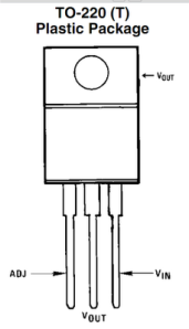
Every project needs a power supply. As 3.3volt logic replaces 5volt systems, we’re reaching for the LM317 adjustable voltage regulator , rather than the classic 7805 . We’ve found four different hobbyist-friendly packages for different situations.
A simple voltage divider (R1,R2) sets the LM317 output between 1.25volts and 37volts; use this handy LM317 calculator to find resistor values. The regulator does its best to maintain 1.25volts on the adjust pin (ADJ), and converts any excess voltage to heat. Not all packages are the same. Choose a part that can supply enough current for your project, but make sure the package has sufficient heat dissipation properties to burn off the difference between the input and output voltages.
Voltage regulator
Schematic of LM317 in a typical voltage regulator configuration, including decoupling capacitors to address input noise and output transients.
The LM317 has three pins: Input, output, and adjustment. The device is conceptually an op amp (with a relatively high output current capacity). The inverting input of the amp is the adjustment pin, while the non-inverting input is set by an internal bandgap voltage referencewhich produces a stable reference voltage of 1.25V. Continue reading
POWER YOUR BREADBOARD WITH USB
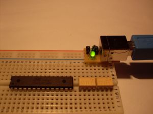
think that it is safe to say that most of the people who make (big or small) electronics-projects have a pc or laptop in theire hobbycorner and a lot of projects need 5V for IC’s or microcontrollers. So using power from a USB cable isn’t that farfetched and lets face it: a lot of devices around us use a USB-connection to get their power or to charge their batteries.
About USB-connectors and power

1.25 V TO 37V – 1.5A VARIABLE, ADJUSTABLE POWER SUPPLY USING LM317
A well designed and variable power supply for electronics hobbyists and DIY’ers is a must, you don’t want to spend a huge amount of money in batteries [On the long run]. A variable power supply can come in handy for testing and powering any project you are building. The mentioned power supply ranges from 1.25V – 37V @ 1.5A using the famous LM317 voltage regulator. LM317T is a very famous IC and easily available in the market comes with 3 pins, supporting input voltage is from 3 volt to 40 volt DC and delivers a stable output between 1.25 volt to 37 volt DC.

THREE REASONS TO TAKE DIY TO THE NEXT LEVEL
Whether you are watching it on television or searching for it on Pinterest, chances are you have admired a few Do It Yourself (DIY) projects recently. Have you taken it a step further and actually completed a DIY project? There are three key reasons why the trend of DIY projects is so popular.
Fun
The first reason that people want to try a DIY project is usually because it sounds like fun. You learn a new skill and the end result will be just what you are looking for. Since Halloween is just around the corner you may be thinking: “Should I go searching for the perfect costume or should I try to design and sew it myself?” Not everyone would have an interest and natural ability in making their own costume so learning to sew would seem like fun. Chances are you are artistic and enjoy ways to tangibly express that creativity. Now imagine taking it one step further and Continue reading
SOUND GIVES OBJECTS A HUMAN TOUCH

Touch screens are so ubiquitous that physical keyboards are becoming a thing of the past, at least for mobile devices. Now imagine if the capability of touch spread from the display to the entire device, allowing control by gently pressing on any part of the phone, or even making any household item into a touch-sensitive interface with your computer.
Anything solid vibrates a specific way when it’s hit physically with another object or with sound waves. The characteristic is called resonance. For example, when you tap on a crystal glass, it vibrates at a certain frequency, producing a ring. If you hit it with sound waves — for example, the ambient background noise in a room — it vibrates at a different frequency. Grip the glass while it rings, and the sound stops. Continue reading
SMART SMOKE ALARM
For a device created to save lives, the household smoke detector sure takes a lot of heat for being annoying: the false alarms when the cookies get burned, the incessant beeping when the battery needs changing and all those times standing on wobbly chairs while trying to find minuscule buttons.

POWER AND THERMAL DISSIPATION
As your embedded project grows in scope and complexity, power consumption becomes an ever more apparent issue. As power consumption increases, components like linear voltage regulators can heat up during normal operation. Some heat is okay, however when things get too hot, the performance of the linear regulator suffers.
How much is too much?
A good rule of thumb for voltage regulators is if the outer case becomes uncomfortable to the touch, then the part needs to have an efficient way to transfer the heat to another medium. A good way to do this is to add a heat sink as shown below.

FLEXIFORCE PRESSURE SENSOR – QUICK START GUIDE
Introduction
This is a quick how-to explaining everything you need to get started using your Flexiforce Pressure Sensor. This example uses the 25lb version, but the concepts learned apply to all the Flex sensors.

Requirements
Necessary hardware to follow this guide:
- Arduino UNO or other Arduino compatible board
- Flexiforce Pressure Sensor
- Breadboard
- M/M Jumper Wires
- 1 MegaOhm Resistor Continue reading
WHY SHOULD YOU DE-RATE CAPACITORS
Capacitors Galore
Capacitors are one of the most common elements found in electronics, and they come in a variety of shapes, sizes, and values. There are also many different methods to manufacture a capacitor. As a result, capacitors have a wide array of properties that make some capacitor types better for specific situations. I would like to take three of the most common capacitors – ceramic, electrolytic, and tantalum – and examine their abilities to handle reverse and over-voltage situations. Note: several capacitors were harmed in the making of this post.

Ceramic Capacitors
The most common capacitor is the multi-layer ceramic capacitor (MLCC). These are found on almost every piece of electronics, often in small, surface-mount variants. Ceramic capacitors are produced from alternating laye Continue reading
UNDERSTANDING POWER FACTOR AND WHY IT’S IMPORTANT
Power factor is a measure of how effectively you are using electricity. Various types of power are at work to provide us with electrical energy. Here is what each one is doing.
Working Power – the “true” or “real” power used in all electrical appliances to perform the work of heating, lighting, motion, etc. We express this as kW or kilowatts. Common types of resistive loads are electric heating and lighting.
An inductive load, like a motor, compressor or ballast, also requires Reactive Power to generate and sustain a magnetic field in order to operate. We call this non-working power kVAR’s, or kilovolt-amperes-reactive.
Every home and business has both resistive and inductive loads. The ratio between these two types of loads becomes important as you add more inductive equipment. Working power and reactive power make up Apparent Power, which is called kVA, kilovolt-amperes. We determine apparent power using the formula, kVA2 = kV*A.
Going one step further, Power Factor (PF) is the ratio of working power to apparent power, or the formula PF = kW / kVA. A high PF benefits both the customer and utility, while a low PF indicates poor utilization of electrical power. Continue reading
RFID TECHNOLOGY
Radio-Frequency Identification (RFID) is technology that allows machines to identify an object without touching it, even without a clear line of sight. Furthermore, this technology can be used to identify several objects simultaneously. RFID can be found everywhere these days – anything from your cat to your car contains RFID technology. This post will cover how RFID works, some practical uses, and maybe even some example code for reading RFID data.

What is RFID?
RFID is a sort of umbrella term used to describe technology that uses radio waves to communicate. Generally, the data stored is in the form of a serial number. Many RFID tags, contain a 32-bit hexadecimal number. At its heart, the RFID card contains an antenna attached to a microchip. When the chip is properly powered, it transmits the serial number through the antenna, which is then read and decoded. Continue reading
HOW IC 555 TIMER WORKS? – DETAILED WALKTHROUGH
Pin-wise functioning of IC555 timer
Pin-1, GROUND: It is the GROUND PIN of the IC. The negative terminal of DC power supply or battery is connected to this pin. Here note that IC555 works always on single rail power supply and NEVER on dual power supply, unlike operational amplifiers.
Also note that this pin should be connected directly to ground and NOT through any resistor or capacitor. If done so, the IC will not function properly and may heat up and get damaged. This happens because all the semiconductor blocks inside the IC will be raised by certain amount of stray voltage and will damage the IC. Refer the block diagram of the IC for more details. For more details read elaborate collection of FAQ on this IC.

Pin-2, TRIGGER It is known as TRIGGER PIN. As the name suggests in triggers i.e. starts the timing cycle of the IC. It is connected to the inverting input terminal of trigger comparator inside the IC. As this pin is connected to inverting input terminal, it accepts negative voltage pulse to trigger the timing cycle. So it triggers when the voltage at this pin LESS THAN 1/3 of the supply voltage (Vcc). Continue reading
PULSE WIDTH MODULATION [PWM]
Pulse width modulation is a fancy term for describing a type of digital signal. Pulse width modulation is used in a variety of applications including sophisticated control circuitry. A common way we use them is to control dimming of RGB LEDs or to control the direction of a servo motor. We can accomplish a range of results in both applications because pulse width modulation allows us to vary how much time the signal is high in an analog fashion. While the signal can only be high (usually 5V) or low (ground) at any time, we can change the proportion of time the signal is high compared to when it is low over a consistent time interval.

Robotic claw controlled by a servo motor using Pulse Width Modulation
Duty Cycle
When the signal is high, we call this “on time”. To describe the amount of “on time” , we use the concept of duty cycle. Duty cycle is measured in percentage. The percentage duty cycle specifically describes the percentage of time a digital signal is on over an interval or period of time. This period is the inverse of the frequency of the waveform.
If a digital signal spends half of the time on and the other half off, we would say the digital signal has a duty cycle of 50% and resembles an ideal square wave. If the percentage is higher than 50%, the digital signal spends more time in the high state than the low state and vice versa if the duty cycle is less than 50%. Here is a graph that illustrates these three scenarios:

LED LIGHT BAR HOOKUP
INTRODUCTION
LED Light Bars are a super-easy way to add some extra-bright and colorful illumination to your project. Each Light Bar is essentially a set of three super-bright 5050-size LEDs. They’re offered in a variety of colors including white, red, blue, and green.

While these bars are very simple devices, they do have a few quirks when it comes to using them. Like the fact that their nominal operating voltage is 12V. In this tutorial we’ll go over some of the important specifications of these LED Light Bars. Then we’ll dive into some example circuits that can help you get the most of these nifty little LED assemblies.
Hardware Overview
A glance at the LED Bars will reveal that there’s not a whole lot required to interface with them. There are two pairs of wire pigtails coming off the sides, labeled ‘+’ and ‘-’. The darker-gray wire connects to the ‘+’ pin, and the white wire connects to ‘-’ on both sides.

LED CURRENT LIMITING RESISTORS
Limiting current into an LED is very important. An LED behaves very differently to a resistor in circuit. Resistors behave linearly according to Ohm’s law: V = IR. For example, increase the voltage across a resistor, the current will increase proportionally, as long as the resistor’s value stays the same. Simple enough. LEDs do not behave in this way. They behave as a diode with a characteristic I-V curve that is different than a resistor.
For example, there is a specification for diodes called the characteristic (or recommended) forward voltage (usually between 1.5-4V for LEDs). You must reach the characteristic forward voltage to turn ‘on’ the diode or LED, but as you exceed the characteristic forward voltage, the LED’s resistance quickly drops off. Therefore, the LED will begin to draw a bunch of current and in some cases, burn out. A resistor is used in series with the LED to keep the current at a specific level called the characteristic (or recommended) forward current.

CONTROLLING BIG, MEAN DEVICES
Microcontrollers are a ton of fun. Once I got hooked, there was no
turning back. Initially playing with sensors and LCDs, I quickly discovered the limits to what a microcontroller could control. A microcontroller’s GPIO (general purpose input/output) pins cannot handle higher power requirements. An LED was easy enough, but large power items such as light bulbs, toaster ovens, and blenders required more sneaky circuitry. Something sneaky called a relay:

In this tutorial we will discuss a small relay board to control the power to a normal AC outlet using 5VDC control.
All the usual warnings apply: Main voltage (120VAC or 220VAC) can kill you. This project, done incorrectly, could certainly burn down your house. Do not work on or solder to any part of a project while it is plugged into the wall – just unplug it!
You can get the Eagle files for the control board here. The control board is composed of a relay along with a NPN transistor and LED. Continue reading
ENGINURSDAY – ON SELF TAUGHT ELECTRONICS
More and more these days, I am meeting people who have built complex, impressive, and clever electronic projects, and, when I ask, I’m surprised to find out that they have no formal engineering or technical education. Now, I’m not surprised because I don’t believe that electronics can’t be learned outside of a university, a good deal of my job is to try to teachelectronics outside a university. I’m surprised because, more often than not, this impressive project will include a design element, component, or concept that I doubt I ever would have been exposed to had I not attended college. How do people learn a complex subject, like say, fourth-order filters, on their own time? I am always blown away by the fact that people have mastered concepts, on their own, that I had never even heard of, let alone attempted to study, before I had the dreadful feeling of finding out that it was one of my required college courses.
Where are these people getting this information?! How did they manage to find such a (sometimes) very dry subject and keep themselves engaged long enough to master it? I ask these questions because I’m jealous. I’m jealous of artists and designers that were exposed to this field at a young age. I’m especially jealous of those lucky people who manage to find just the right book, or mentor, or resource to teach them and keep them engaged in a subject that, in college, I paid a boatload of money for someone to teach me. Continue reading
SKIN TATOO TAKES BODY TEMPERATURE

When it comes to grafting electronics onto skin, John Rogers from the University of Illinois at Urbana-Champaign churns out epidermic tech at a seemingly fevered pitch. Perhaps his latest creation will make sure he doesn’t overheat.
Along with a team of researchers from the U.S., China, and Singapore, Rogers has designed an extremely pliable patch that, when applied to the skin, can accurately measure skin temperatureand Continue reading
CONNECTING A RELAY TO ARDUINO

Why use a relay with an Arduino board?
Individual applications will vary, but in short – a relay allows our relatively low voltage Arduino to easily control higher power circuits. A relay accomplishes this by using the 5V outputted from an Arduino pin to energize an electromagnet which in turn closes an internal, physical switch attached to the aforementioned higher power circuit. You can actually hear the switch *click* closed on even small relays – just like the big ones on street corners used for traffic signals. Continue reading
A MICRO RELAY AT WORK
A relay is an electrically operated switch. Many relays use an electromagnet to operate a switching mechanism mechanically, but other operating principles are also used. Relays are used where it is necessary to control a circuit by a low-power signal (with complete electrical isolation between control and controlled circuits), or where several circuits must be controlled by one signal. The first relays were used in long distance telegraph circuits, repeating the signal coming in from one circuit and re-transmitting it to another. Relays were used extensively in telephone exchanges and early computers to perform logical operations.


GARAGE CAR DETECTOR WITHOUT A MICROCONTROLLER

At the end of this instructable you will be able to detect your car as it approaches the wall inside your garage, signalling you that the car is inside far enough so you can close the door.
Most car sensors will use a microprocessor to help calculate the distance of an approaching car when entering the garage.
The main component and the challenge was to use a 555 timer as the driving “brains” of the project. So here we go: Continue reading
RC CIRCUIT FOR BIBBERBEEST/ VIBROBOT
Lets now start of with a new series – “Hobby DIY Electronics” which contains small projects to start for beginners, robotics and much more. Enjoy the series of upcoming posts and do leave your experiences and messages in the comments section below.

Making Bibberbeests with kids is a HUGE success at schools, parties and festivals
Now what is more fun than a Bibberbeest? A remote controlled bibberbeest, using a standard audio/video RC?
So what I needed was a receiver circuit for a standard TV RC that can switch on and off a Bibberbeest’s motor, working on 3 Volts max.
At first I was tempted to go the microcontroller way, But in my eternal search to keep things simple, I eventually decided to use a hardware-only circuit: Just eight parts on a 2,5 x 4 cm board (1″ x 1,5″).
After some trial and error I used this IR toggle switch diagram (with slight mods) around a 555 timer chip by member BIC, which works quite well.
Step 1: Tools and materials

REPLACING A BATTERY PACK WITH CONSUMER AAA RECHARGEABLE NiMH BATTERIES
Recently I wanted to replace a rechargeable battery pack from a RC car. I tried getting a rechargeable battery pack similar to the original one but that didn’t last even half the period the original one had lasted. So I had to find out an economical way of getting batteries replaced.
Instead of taking a chance on another unreliable replacement battery pack, I decided to look inside the existing one. The plastic shell consists of two parts held together with transparent tape that is easily removed with a razor blade. Inside, there are three industrial tabbed cells of the same length and diameter of consumer AAA cells, without the bump on the positive terminal.

Given the identical cell size, it distresses me that the manufacturer didn’t simply mold a AAA battery holder into the handset. This consumer-friendly feature would have allowed the end user to replace the individual cells using off-the-shelf consumer batteries. The idealist assumes this is a safety feature to prevent errant installation of alkaline cells or mixed chemistries that might catch on fire when recharged from the base. Continue reading
ADAPTIVE VEHICLE LIGHTING SYSTEM
When a vehicle is driven on the highway at night, it is required that light beam should be of high density and should illuminate the road at a distance sufficiently ahead. However, when a vehicle coming in the opposite direction approaches the vehicle with a high-beam headlight, driver of that vehicle will experience a glare, which may blind him. This dazzle effect is one of the major problems faced by a driver in night driving. To avoid this impermanent blindness, a separate filament is usually fitted in the “dual-filament” headlight bulb in a position such that light beam from this second filament is deflected both down and sideways so that the driver of the oncoming car is not blinded. In practice, one mechanical dimmer switch is used by the driver to manually select high (bright) or low (dim) headlight beam. However, this is an awkward task for the driver especially during peak traffics.

Our project “Adaptive Lighting System for Automobiles” is a smart solution for safe and convenient night driving without the intense dazzling effect and aftermaths. Adaptive Lighting System for Automobiles needs no manual Continue reading
WEARABLE LIGHT ORGAN
This simple, wearable circuit uses an operational amplifier (or “op-amp”) chip to convert sound into light. An LM324 op-amp and a transistor boost input from a mini condenser microphone to light a series of LEDs. Watch it blink to the beat of your favorite music.
STEPS
Components Required
- Battery, 9V (1)
- Solder, lead-free (1)
- Battery snap, 9V (1)
- Hookup wire, 22 gauge, multiple colors (1)
- PC board, grid style, with 371 holes (1)
- Resistor assortment, 500 piece (1)
- Transistor, NPN, 2N4401 (1)
- Microphone condenser element (1
- Capacitor, 0.1 µF ceramic (100 nF, capacitor code 104) (1)
- Capacitor, 1.0µF non-polarized electrolytic (capacitor code 105) (1)
- Op-Amp chip, Quad, LM324 (1)
- LED 5mm (1)
Step #1: Gather the parts

- The electret microphone element is polarized, so be careful not to reverse the connections. The ground leg is the one with the 3 silver traces running to the case (second photo).
- To identify resistor values from their color codes, you can use this online calculator.
- The LM324 chip has four op-amps, but this circuit only requires two of them. Continue reading
SUNSET LAMP

LDR-based automatic lights flicker due to the change in light intensity at dawn and dusk. So compact fluorescent lamps (CFLs) are unsuitable in such circuits as flickering may damage the electronic circuits within these lamps. The circuit described here can solve the problem and switch on the lamp instantly when the light intensity decreases below a preset level. The circuit uses popular timer IC NE555 (IC1) as a Schmitt trigger to give the bistable action.
The set and reset functions of the comparators within the NE555 are used to give the instantaneous action. The upper threshold comparator of IC1 trips at 2/3Vcc, while the lower trigger comparator trips at 1/3Vcc. The inputs of both the threshold comparator and the trigger comparator of NE555 (pins 6 and 2) are tied together and connected to the voltage divider formed by LDR1 and VR1. The voltage across LDR1 depends on the light intensity. Continue reading
PERIODICALLY ON OFF MOSQUITO REPELLANT

Some of the mosquito repellents available in the market use a toxic liquid to generate poisonous vapours in order to repel mosquitoes out of the room. Due to the continuous release of poisonous vapours into the room, after midnight the natural balance of the air composition for good health reaches or exceeds the critical level. Mostly, these vapours attack the brain through lungs and exert an anesthetic effect on mosquitoes as well as other living beings by small or greater percentage. Long exposure to these toxic vapours may cause neurological or related problems.
Here is a circuit that automatically switches on and off the mosquito repellent after preset time interval, thus controlling the release of toxic vapours into the room. Continue reading
PHONE POCKETS HIDES YOU FROM LOCATION TRACKERS

You’re being tracked and not necessarily anonymously. A study last March from researchers at MIT’s Media Lab showed that so-called “anonymized” cell phone data is not so anonymous. The researchers were able to extract specific location information for individuals carrying phones with GPS and location services on. If this concerns you, you might want to keep an eye on New York-based artist and technologist Adam Harvey, who just launched a Kickstarter program to develop phone pockets that shield your phone’s cellular, Wi-Fi, and GPS signals.
According to PopSci, the slip cover is based on the technology behind the electric field-blocking Faraday cage, which protects electrical equipment from lightning strikes. Like the cage, the Off Pocket contains a metal fiber mesh that blocks the wireless signals (frequencies between 800MHz and 2.4 GHz) Continue reading
POCKET SIZED POWER SUPPLY

I am a big fan of garage sales, flea markets, and thrift stores. They are great places to find used parts and materials for your next project. But one problem that I often run into is not being able to test battery powered electronics to see if they work. Because there are so many different combinations of batteries that are used in portable electronics, it isn’t really practical to carry around batteries for testing. One device may need 6 AA’s and another may require 4 D’s. So I came up with this simple pocket-sized variable power supply. It can plug into either a 9V battery or a 12V battery pack. You can then adjust the output voltage to match the device that you want to test and attach the output wires to the end terminals on the device’s battery connectors. This lets you power the device long enough to see if it works.
COMPONENTS REQUIRED
- 8-Position DIP Switch
- 220 ohm Resistor
- 1 µF Capacitor
- 0.1 µF Capacitor
- LM317 Adjustable Voltage Regulator
- 2 x Alligator Clip Wires
- Perf Board
- 9V Battery Connector
- 270 ohm Resistor (preferably 1/8 watt) (7)
- Soldering Iron and Solder
STEPS
Step #1: Materials

- LM317 Adjustable Voltage Regulator, 0.1 µF Capacitor, 1 µF Capacitor, 220 ohm Resistor, 7 x 270 ohm Resistor (preferably 1/8 watt), 8-Position DIP Switch, Perf Board, 9V Battery Connector, 2 x Alligator Clip Wires, Continue reading
COMPUTER PRINTER SALVAGE

It’s easy to build up a “junk box” of items you can use to build projects seen in just about any-thing you can imagine.
Many of my articles take advantage of found components, often picked out of trash bins. Just because an electronic device has failed at its original task doesn’t mean it can’t perform other tasks. Castoffs can be recovered and the parts repurposed in countless ways.
Recently, my trash-picking adventures turned up a discarded laser printer. I set about finding what wonders were waiting beneath the plastic covers.
JACKPOT OF PARTS
My first discovery was the main circuit board. Once I stripped the heat shields off, I found over 50 nonproprietary electronic parts, including capacitors, resistors, voltage regulators, transistors, transformers, coils, and integrated circuits. Jackpot! A couple of boards like this, and you’re on your way to building a backup supply of parts for future projects. A second, smaller PC board also yielded numerous useful components. Continue reading
MINI ROVER SURVEILLANCE BOT

Click the picture to view the MINI ROVER in action
Ever wanted to explore your house from a pet’s perspective, here’s the Mini Rover Surveillance bot which is going to do exactly that.
STEPS
Step #1: Strip down the car.


- Using Scientific Toys’ EZTEC-branded 1:17 scale Chevy Silverado R/C car as a camera platform. This toy is cheap, hacker-friendly, and works astoundingly well for the price.
- First, detach the truck body shell from the chassis by removing 3 screws: 2 on top, in the truck bed, and 1 from below, between the front wheels.
- Now, open the electronics compartment by removing 4 screws, as shown, and lifting the plastic cover gently up and off. The floppy wire antenna, which is threaded through a hole in the cover, should slip out the bottom as you do this.
Step #2: Install the chassis standoffs.


- Position the video camera mounting base on the car’s electronics compartment cover, as shown. Use the base as a template to drill 3 matching 5/32″-diameter holes in the electronics compartment cover.
- TIP: You may find it easier to operate the drill through the baseplate if you remove the camera mount ball joint at the top of the stem first. Simply turn the wingscrew all the way out and the whole assembly will come off.
- Turn the electronics compartment cover over, and attach three 10cm standoffs on the top side of the compartment cover using the screws that come with the standoffs. Continue reading
LED ILLUMINATION FOR REFRIDGERATORS
The incandescent lamp provided inside the refrigerators glows whenever we open the door. It suffers from several disadvantages like:
1. Being a single light source, located in the upper corner, light does not spread uniformly. Only upper shelves get good light and the lower shelves are in darkness because of the shadows of food items kept.
2. Ironically, the lamp generates heat in the space which we are trying to cool, thus making the compressor work for longer duration.
3. During power outages, there is no illumination inside the fridge, when it is most needed.
The above problems could be overcome by using a distributed array of LEDs with battery back-up, which provides shadow less light and cool operation.

Fig. 1: Rows of LEDs placed in PVC channels

Fig. 2: Orientation of LEDs and the arrows indicating the direction of light from LEDs
Two columns of six white LEDs in each row (2×6 array of white LEDs) are made using white PVC channels. The length of the channel equals the height of the cooling compartment of the fridge. The LEDs are placed such that each shelf has two LEDs located at the top corner. These channels are placed in the left- and right-hand corners inside the fridge as shown in Fig. 1. Continue reading
ELECTRONIC REMINDER CIRCUIT

This easy-to-build electronic alarm will remind you of an impotant task after a preset time. It is particularly useful for housewives and busy professionals. All you have to do is set the time in minute swith the help of two thumbwheel switches (S3 and S4) and press and release start switch. Precisely after the time set by you is over, there is an audio as well as visual indication to remind you that the time you set has elapsed. The gadget is portable and operates off a 9V battery.
At the heart of this circuit are two counter ICs CD4029 (IC4 and IC5). These are programmable up/down 4bit binary/decade counters belonging to CMOS family of digital integrated circuits. The information present on them is fed to inputs P0 through P3 in parallel. It is loaded into the counter when the PL input is high, independent of the clock pulse input. In this circuit, IC4 and IC5 count in up/down mode when the up/down input is high/low. These have been wired as 4-bit binary counters in countdown mode with B/D input low. The counter advances by one count on every low-to-high transition of the clock pulse. Continue reading
Solar-Powered Laptop Lasts 10 Hours on a Charge

What if it only took two hours out in the sun supply your laptop with 10 hours of battery life? That’s what the Ubuntu-driven laptop aims to do, according to the folks over at WeWi Telecommunications Inc.
The Sol, a rugged-looking laptop with built-in foldable solar panels, is designed for use in the military, education and developing countries where electricity is scarce. The Canada-based makers behind the Sol claim that the device can run directly off solar energy or can harness the sun’s rays to charge the laptop’s battery in under two hours. Once fully charged, the battery is expected to last between eight and 10 hours.
Packing mid-range specs, the Sol comes with a 1.86GHz dual-core Intel Atom D2500 processor with 2GB of RAM upgradeable to 4GB, a 320GB SATA HDD from Seagate, GMA3600 graphics, a 13.3-inch LCD screen with a 1366 x 768 resolution, and a 3-megapixel camera. It also features a USB 2.0 port, an audio jack, HDMI, Ethernet and SD card ports like most standard laptops. Wi-Fi, GPS and Bluetooth will come built-in to the Sol, and it will be available in 3G and 4G LTE configurations as well. The Sol will run for $350 but you can also snag a waterproof edition for $400, and its slated to launch in Ghana, Africa first. Continue reading
Disposable Drones Take Flight
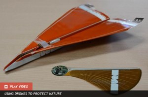
When we think of drones — nay unmanned aerial vehicles — we typically picture military drones or those ubiquitous quadrotors. However, two new mini-drone designs are taking shape: a paper airplane and a maple seed.
a team of roboticists created both designs to help record atmospheric conditions in the event of a forest fire. The disposable, self-steering drones are essentially sensor modules that can be dropped over a forested area to relay environmental data that could indicate potential for fire.
The first prototype looks exactly like a standard paper airplane, only this one’s made of biodegradable cellulose material. Once deployed from a larger aircraft, the so-called Polyplane drone steers itself using tabs attached to the back of each wing. An onboard control system bends each tab to direct the craft as close as possible to a pre-determined landing area. Because the circuits Continue reading
